Simon Kirby, 2008-08-24
This page explains how I replaced/repaired a shutter unit in a Canon EOS 20D. This is in no way sponsored or approved by Canon, but I hope that it can be of use to anybody who may want to attempt this themselves (or to help anybody who might have tried or might want to change the shutter button or LCD cover or any other part that might be along the way). Follow at your own risk, of course!
WARNING: The flash capacitor can seriously zap you if not properly discharged. This procedure requires reasonable soldering and electronics experience. You will need (at least) a soldering iron, desoldering iron/wick, miniature Philips screw driver (No. 0), and likely some pliers, tape, magnifier, auxiliary lighting, paper towel, etc.
Back in September, 2004, we got our paws on a new Canon EOS 20D digital SLR body. This camera has served us well over the years and was a great improvement over the 10D in sensor noise and write speed. We have taken many beautiful pictures with it as can be found on our daily photoblog, Pleasantly Tilted.
One day, the second-last day of our trip through Costa Rica and Panama, right after this shot, "Err 99" flashed on the LCD:
 Yes, right after shooting a black Vulture. Fitting, indeed!
No amount of lens changing, battery replacement, flash card replacement, or anything I could think of would make it work again. Sensor clean mode would clear the mirror but not open the shutter. Based on past experience, I guessed that the shutter unit had failed. Canon Canada's Service Department confirmed that this was likely the case, and gave the option to send the camera in for repair, which would come to about CAD$350 after parts and labour.
Previously, our EOS 10D shutter had also warn out, after nearly the same number of shots. At the time we were not aware that parts were available individually, and based on the age and condition of the cameras and price of new bodies available, it was a tough call. Finally, we decided to send it in for repair for CAD$364.65. The camera came back with a clean sensor and in perfect working order, and is still taking pictures today. We were very happy with the service, but we could almost have purchased a new (slightly lower end) camera for the same price.
Since then, I had found this page where somebody had replaced the 10D shutter themselves. I am somewhat electronically-inclined, so I figured ...How hard could it be? I was not able to find any pages specific to the 20D, but I figured that it was likely very similar. I found an EOS 20D Parts Catalog on the web and found the part number. I spoke with Canon's Parts Department (who can look up the part numbers for you anyway) and ordered:
| Part | Price |
|---|---|
| EOS 20D shutter (CG2-1317) | $47.25 |
| EOS 20D LCD window (CB3-1831) | $13.69 |
The parts arrived shortly and I prepared to undertake the replacement.
In April, 2008, I successfully replaced the shutter (and back LCD plastic, since it was a little scratched). Not bad for the price and three nights of my time! The old shutter appeared to be working mechanically, but a small gold-plated contact switch from the side had broken off (and fell out when I opened the camera). The new part that I had received from Canon appears to have beefier gold-plated parts -- it seems they have made an improvement!
In summary, the 20D is similar but unfortunately a little more difficult than the 10D because the main frame that runs behind the mirror box is behind the shutter, and the sensor mounts to the other side (between the mirror box and the frame). Since the frame holds _everything_ else, the 10D design is a little easier for this task.
10,000 shots later in August, 2008, the shutter started to intermittently fail again. I decided to take apart the camera one more time (how hard could it be -- I've already done it once!) and see if I could find out what was wrong. I took the shutter back out again and looked at it -- it all seemed fine. I reassembled the entire camera again, thinking perhaps the problem was electrical. After reassembly, the problem continued to occur at exactly the same rate -- every other shot or so, "Err 99". So, I took the camera all the way back apart again -- this time, documenting with pictures (and this web page).
This time, the shutter did not have anything obviously wrong with it. I measured resistance across the gold-plated contacts and that seemed fine. I even moved it by hand -- it seemed fine. For lack of a better idea, I decided to move a gold-plated contact from the "new" (but now failing) shutter to the old shutter, where the contact had broken off. In the end, it worked! Here's how I did it.
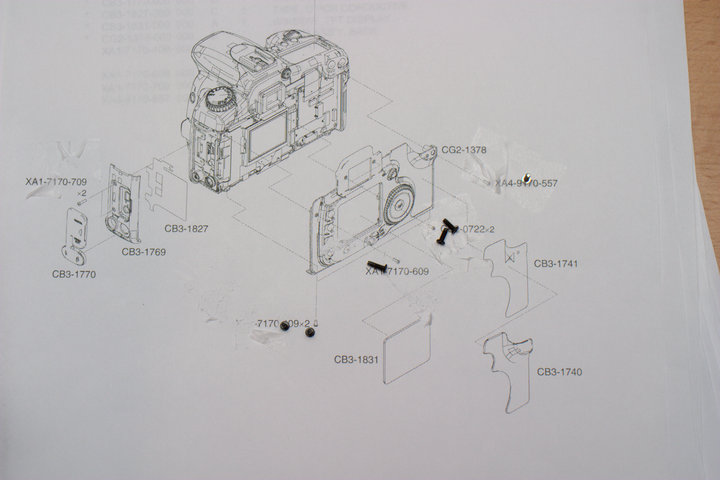
First, prepare a clean, well-lit working surface free of dust, debris, and carpet that swallows screws (ugh...). On my first attempt, I had no idea how many screws I would be encountering, so I tried to line them up beside all of the pieces that I removed. This turned out to be a nightmare upon reassembly, since there are a LOT of different screws -- lengths, pitches, head sizes and types, and colours. This time, I printed out the EOS 20D Parts Catalog (link above) and taped the screws to the page as I went. This worked out well.
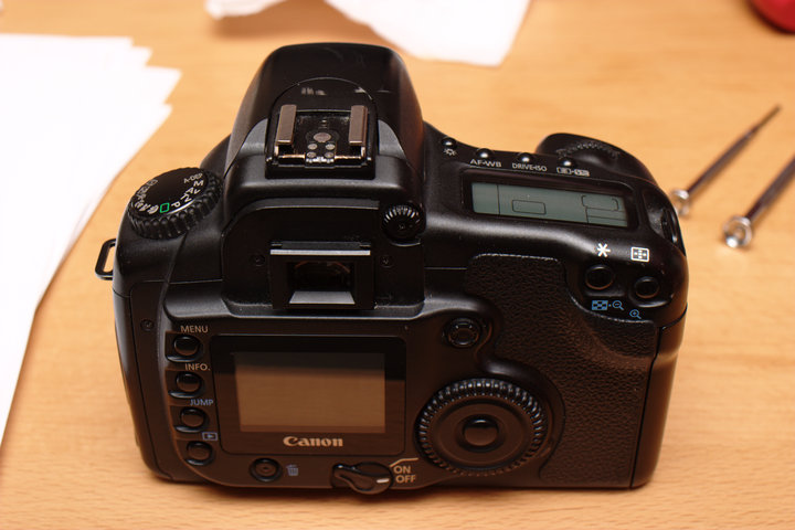
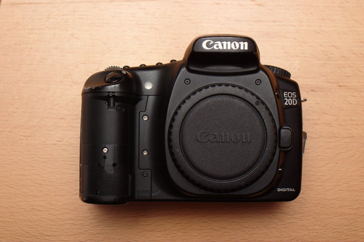
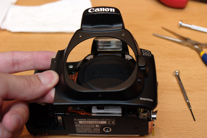
Here it is before the event. Please ignore the scratches and dings -- it has had a hard life. :) I think I probably would have killed a Rebel long ago. This one has been lightly drowned, dropped, and kicked around a little bit.
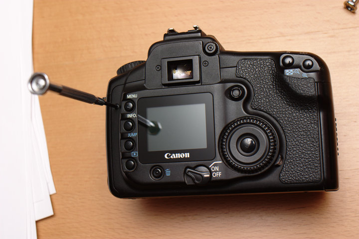
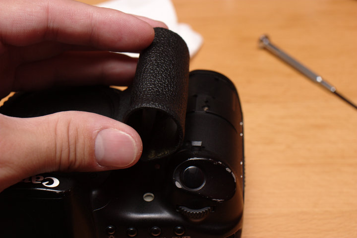
First, remove the batteries (main and clock), and make sure everything is unplugged and clear. Remove the strap as it it will get in the way. Remove the eyepiece (it slides up and off). I have the front grip removed here too, but it can be removed later as needed. there is adhesive on the back that appears to re-stick fairly well, but this part could always be reordered as well if it is warn.
 Start by removing the back cover screws. There is one on the left, two at the top
(under the eyepiece), one under the top right of the rubber grip, and two
on the bottom.
Start by removing the back cover screws. There is one on the left, two at the top
(under the eyepiece), one under the top right of the rubber grip, and two
on the bottom.
 Here is how I kept track of the screws. Do this or something like it,
or you will spend forever trying to figure out where they came from. I
put tape over them so that I could move the pages around.
Here is how I kept track of the screws. Do this or something like it,
or you will spend forever trying to figure out where they came from. I
put tape over them so that I could move the pages around.
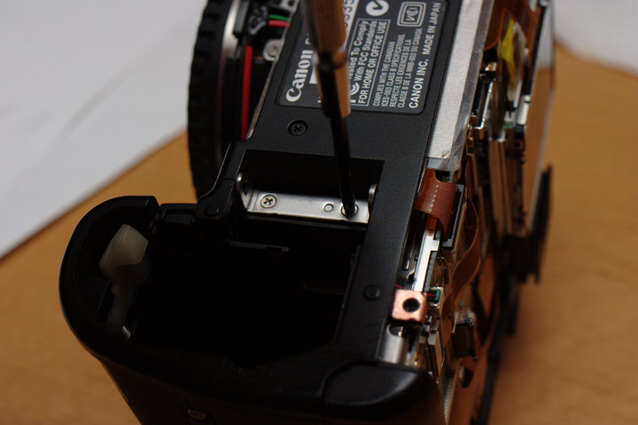
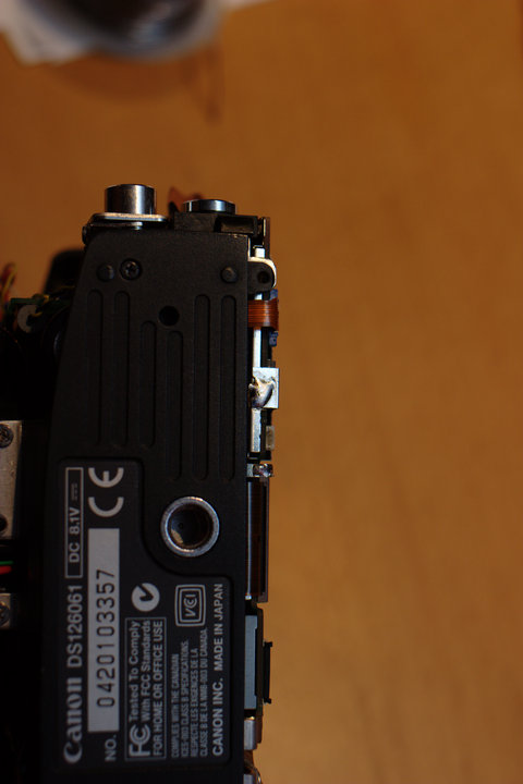
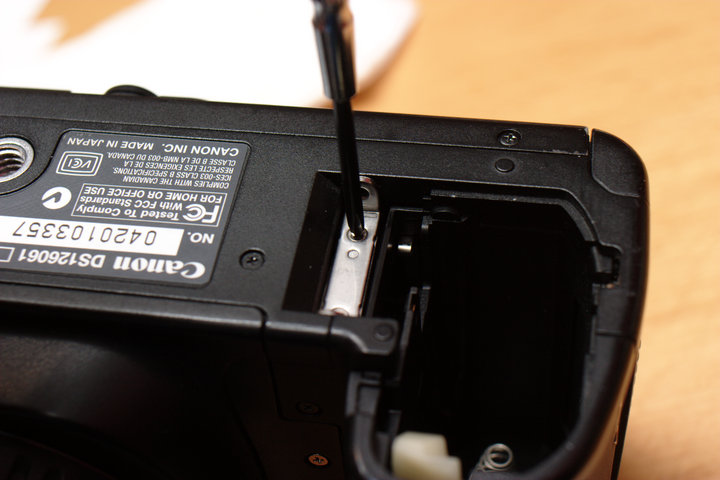
 You will not be able to remove the back until the output panel on the
left (from the back) has been loosened. Remove the two screws under the
rubber cover.
You will not be able to remove the back until the output panel on the
left (from the back) has been loosened. Remove the two screws under the
rubber cover.
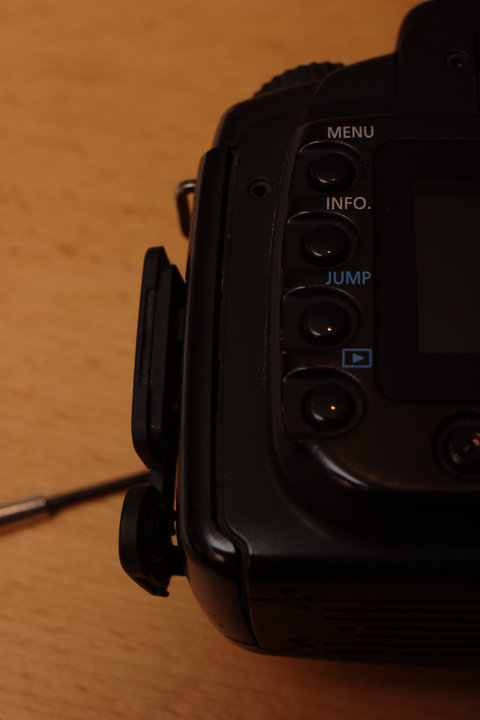
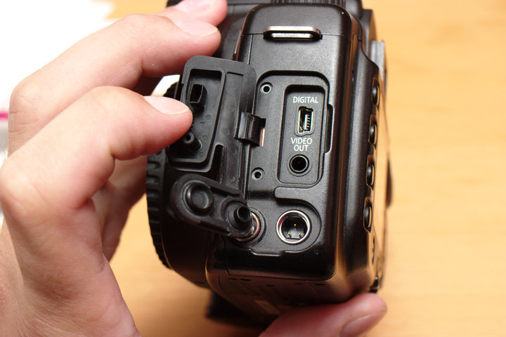
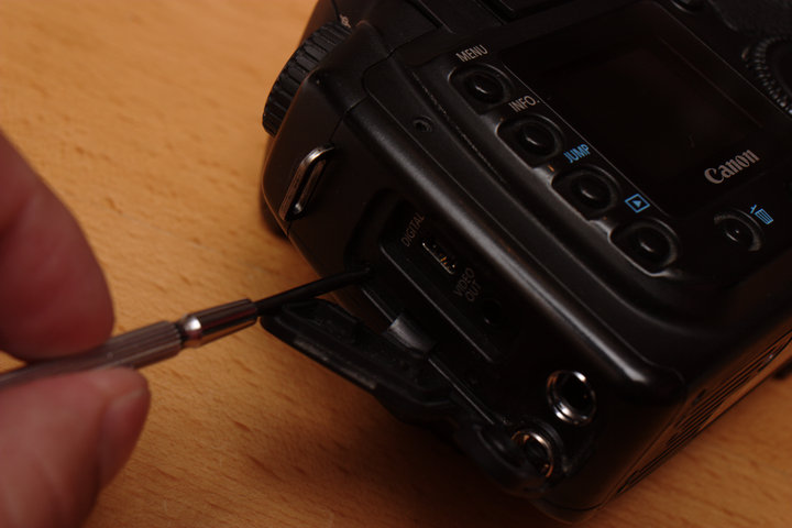 Then, pull it out a little to allow the lip to come out:
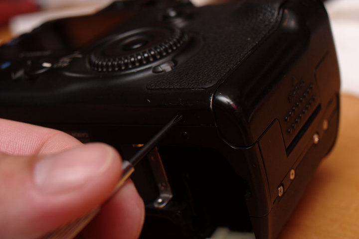
 You should now be able to flap open the back. Be careful of the ribbon
cable on your right side.
You should now be able to flap open the back. Be careful of the ribbon
cable on your right side.
 If you have not seen these connectors before, they are pretty easy once
you get the hang of them. In this case, slide your finger nail (or other
flat, gentle instrument) in from the right side and lift up the black
lever. This should allow the cable to slide out and free the back panel.
If you have not seen these connectors before, they are pretty easy once
you get the hang of them. In this case, slide your finger nail (or other
flat, gentle instrument) in from the right side and lift up the black
lever. This should allow the cable to slide out and free the back panel.
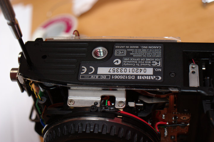
 Turn the camera over and remove the front grip if you have not already.
 Remove the two screws on the left of the lens mount, two above the lens
mount, and one under the lens mount and remove the front piece.
Remove the two screws on the left of the lens mount, two above the lens
mount, and one under the lens mount and remove the front piece.
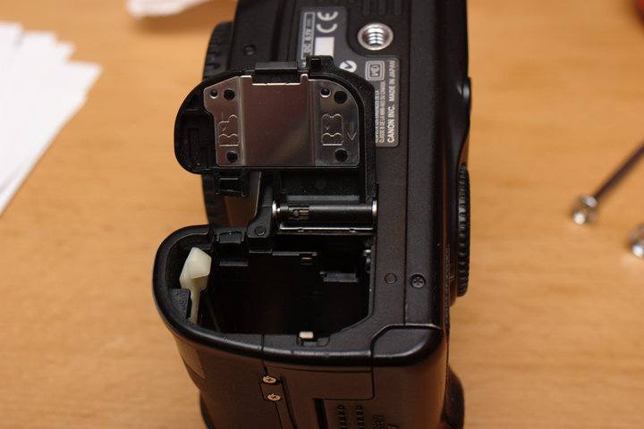
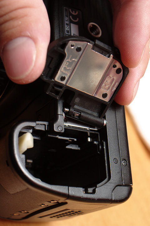
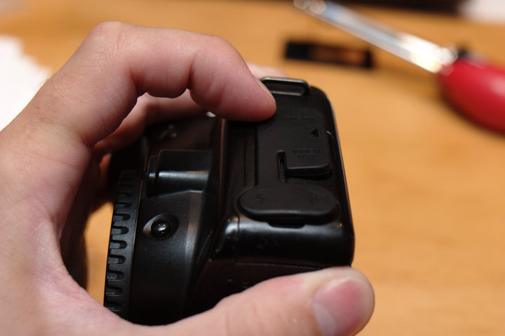
 Turn the camera over and open the battery compartment door. Remove the
door by sliding the lever on the axle away from the closest side. It
should come out easily.
Turn the camera over and open the battery compartment door. Remove the
door by sliding the lever on the axle away from the closest side. It
should come out easily.
 Remove two screws and the C-shape bracket that normally holds the door.
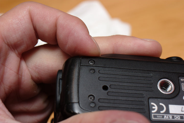
 Remove the two screws attaching the bottom plastic cover and remove the
cover. The battery side may get a little caught, but it should come.
Remove the two screws attaching the bottom plastic cover and remove the
cover. The battery side may get a little caught, but it should come.
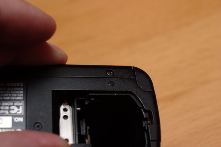
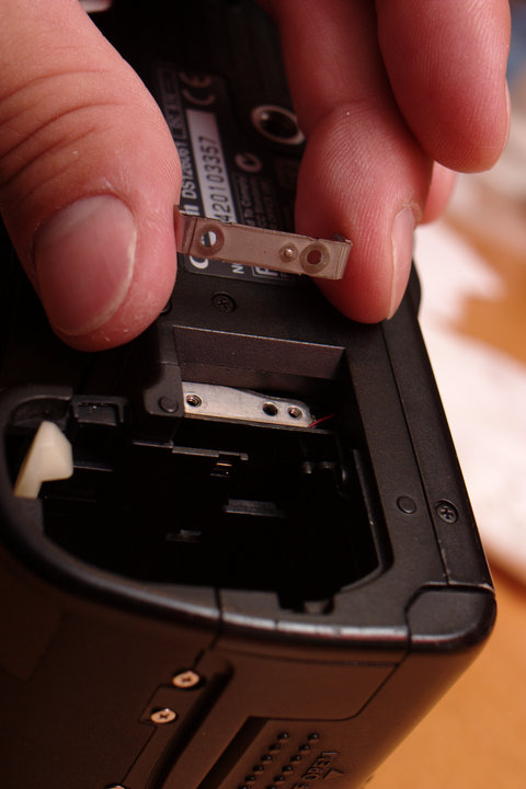
 Remove the metal/plastic pad there is a section of adhesive on it.
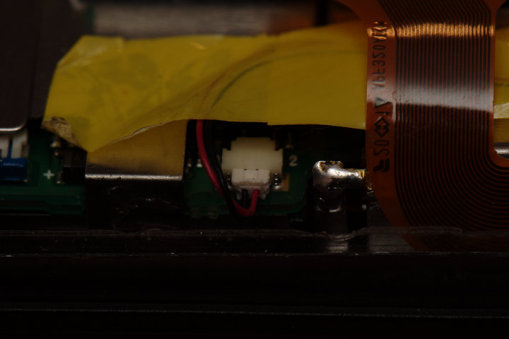
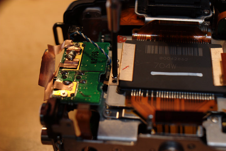
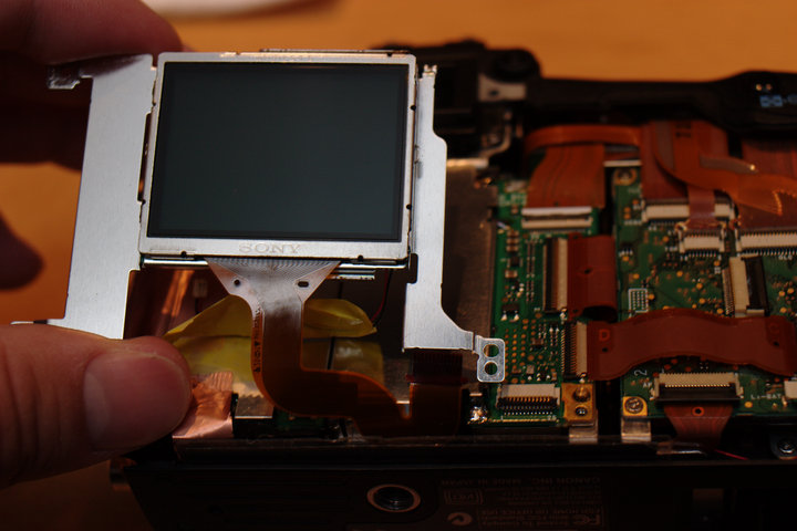
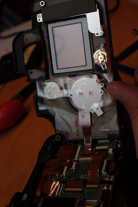
 Turn the camera back over and get ready to remove more of the components,
starting with the LCD monitor. Be sure to open the connectors by lifting
up the black arm. The LCD should have a main ribbon and a backlight
power connector.
Turn the camera back over and get ready to remove more of the components,
starting with the LCD monitor. Be sure to open the connectors by lifting
up the black arm. The LCD should have a main ribbon and a backlight
power connector.
 Unfortunately, we will need the soldering iron / desoldering iron
already. If you have both or desoldering wick, you will be able to do a
better job than if you are using just an iron.
Unfortunately, we will need the soldering iron / desoldering iron
already. If you have both or desoldering wick, you will be able to do a
better job than if you are using just an iron.
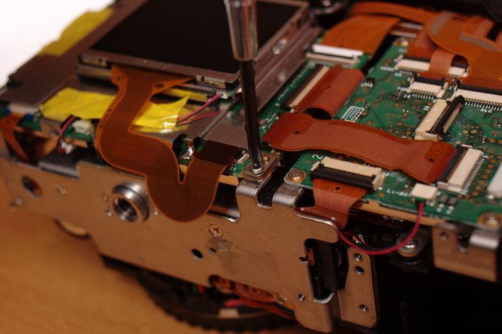
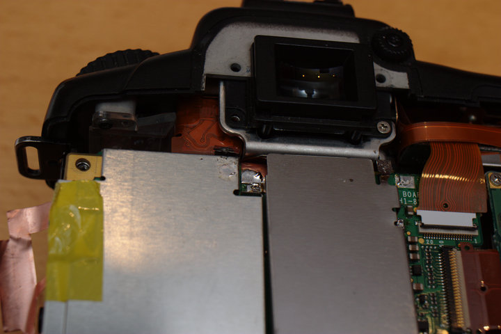
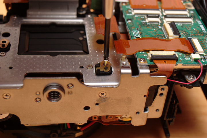
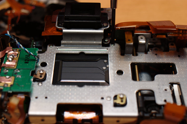
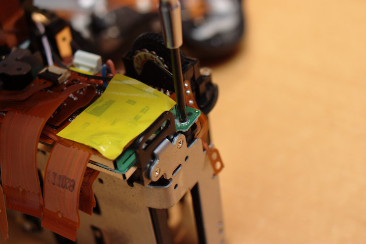
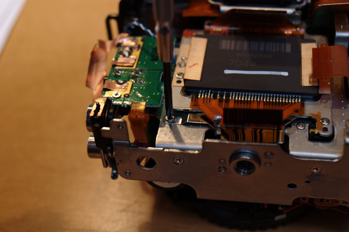
Start by removing the lower two screws holding the LCD unit in place. The top left screw is an already-removed cover screw.
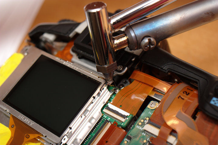
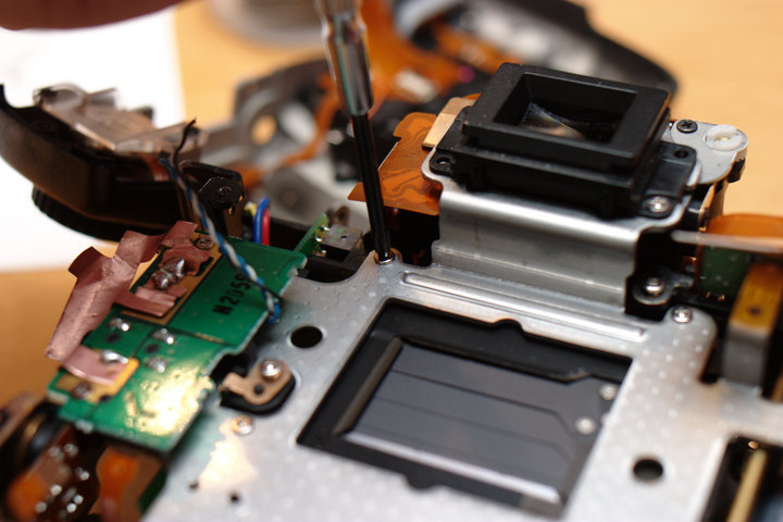
 Remove the solder from the top right of the LCD unit and remove the LCD
unit.
Remove the solder from the top right of the LCD unit and remove the LCD
unit.
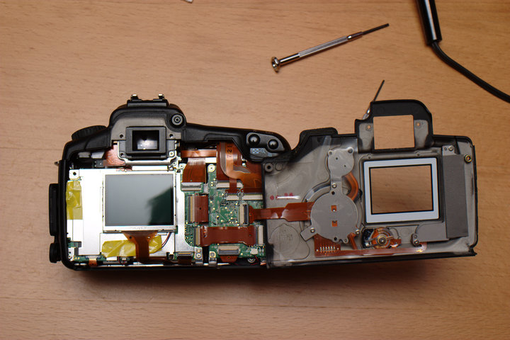
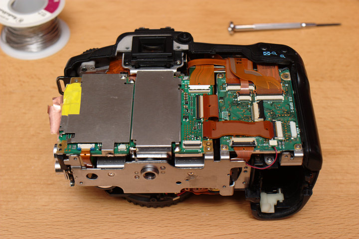
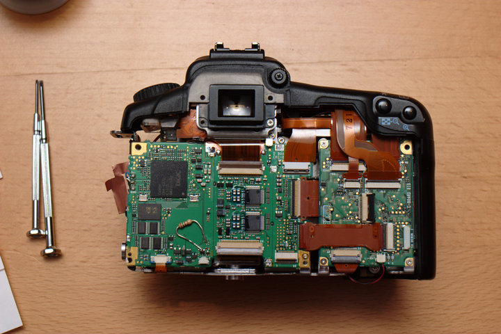
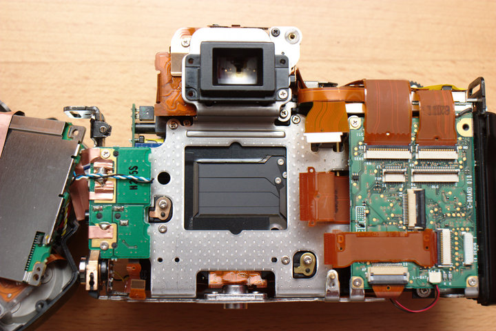
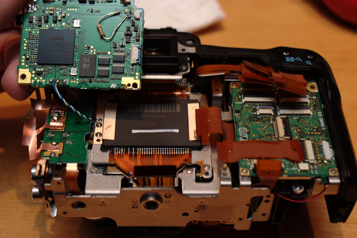
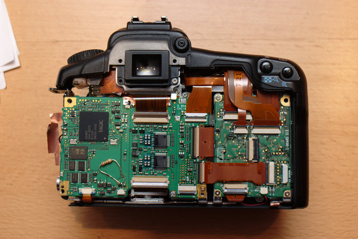
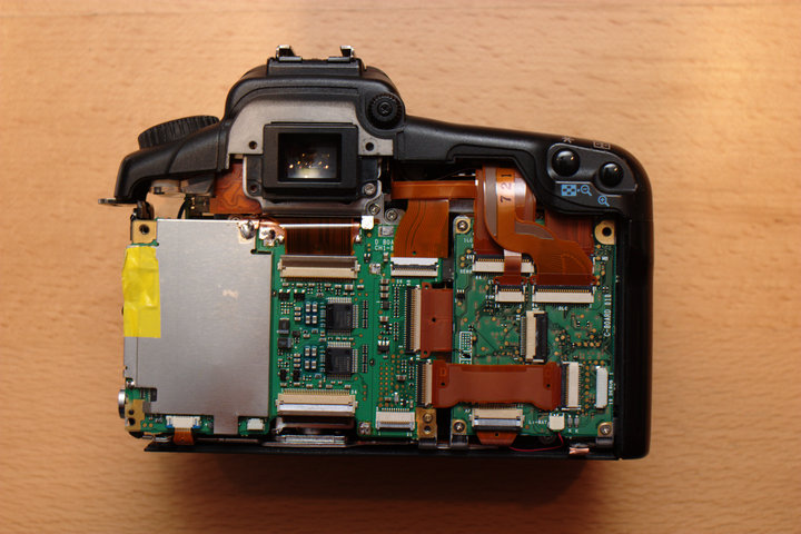
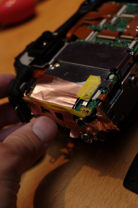
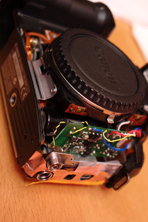
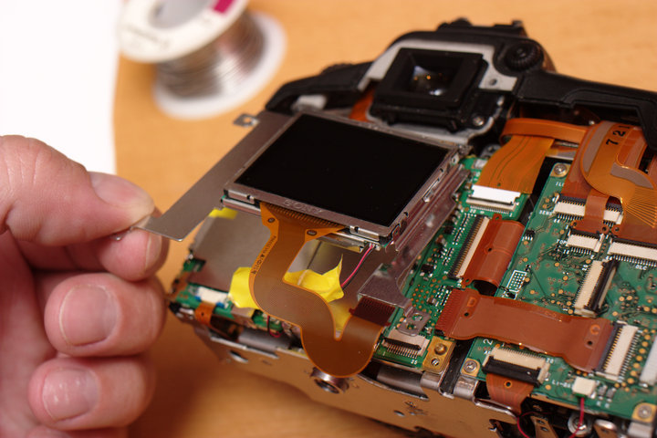 Your camera will now look like this. (There will probably be some copper
shielding tape on the left/bottom that you may have had to remove
already. I forgot to put it back last time.)
Your camera will now look like this. (There will probably be some copper
shielding tape on the left/bottom that you may have had to remove
already. I forgot to put it back last time.)
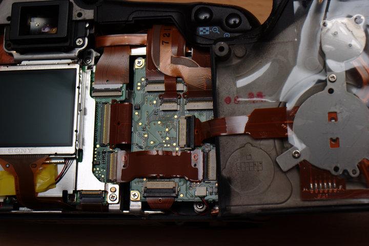
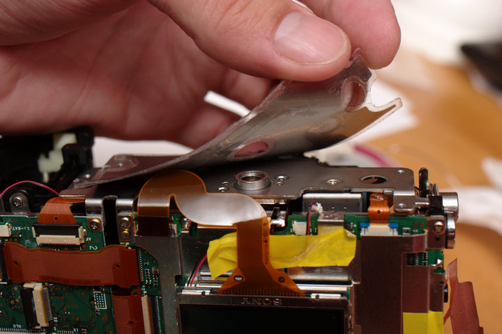
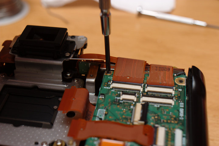
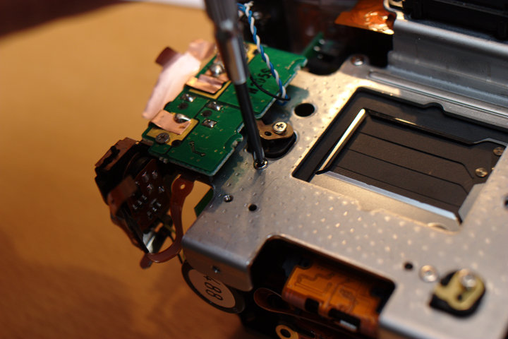
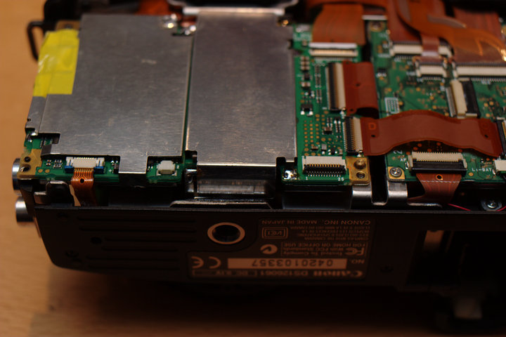
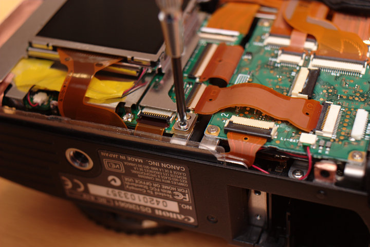
 Work your desoldering iron around the center metal shielding on the left
main board. This covers the CMOS sensor cable connectors which need to
be freed before the board can be removed. Remove the shielding by
carefully removing the solder and walking the board up with some light
leverage while heating the joints.
Work your desoldering iron around the center metal shielding on the left
main board. This covers the CMOS sensor cable connectors which need to
be freed before the board can be removed. Remove the shielding by
carefully removing the solder and walking the board up with some light
leverage while heating the joints.
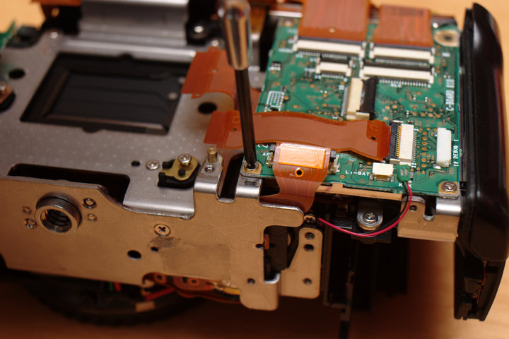
 In hindsight, I do not think the left shielding even needs to be removed.
However, I did here. There were two points on the side that were
soldered and one leg to the board right on the left.
In hindsight, I do not think the left shielding even needs to be removed.
However, I did here. There were two points on the side that were
soldered and one leg to the board right on the left.
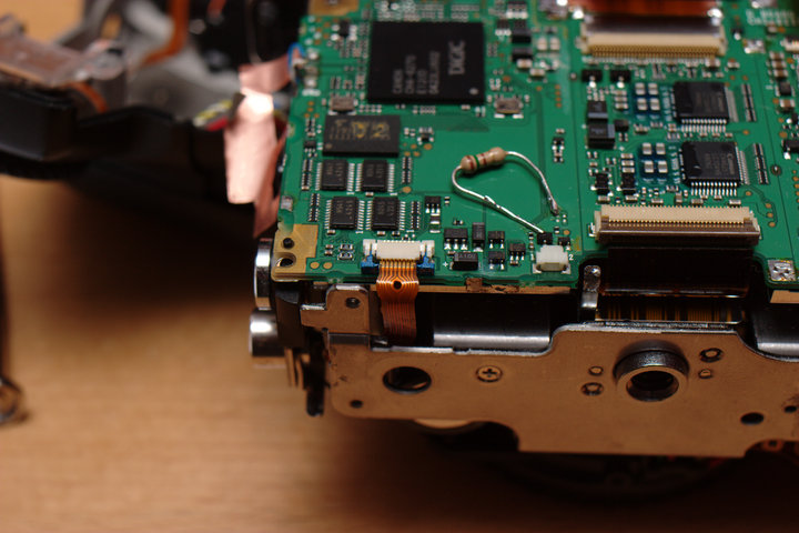
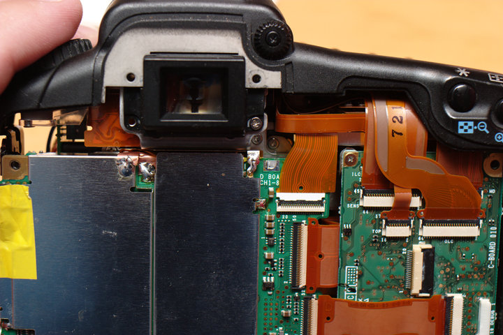
 Your camera should now look like this, less the out-of-place resistor.
I added that last time to make the LCD a little brighter. Nothing to see
here, move right along...
Your camera should now look like this, less the out-of-place resistor.
I added that last time to make the LCD a little brighter. Nothing to see
here, move right along...
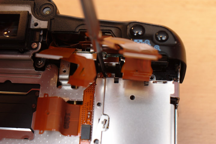
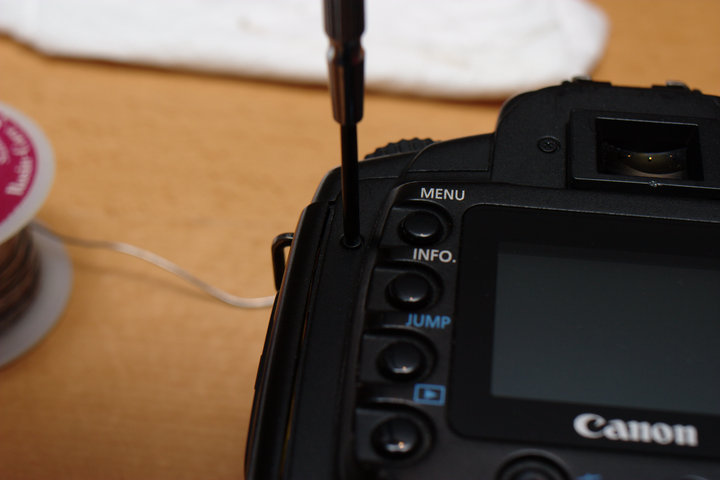
 Prepare to remove the front side hand grip by removing the two screws on
the side, one on the front, and one on the lower front near the lens
mount.
Prepare to remove the front side hand grip by removing the two screws on
the side, one on the front, and one on the lower front near the lens
mount.
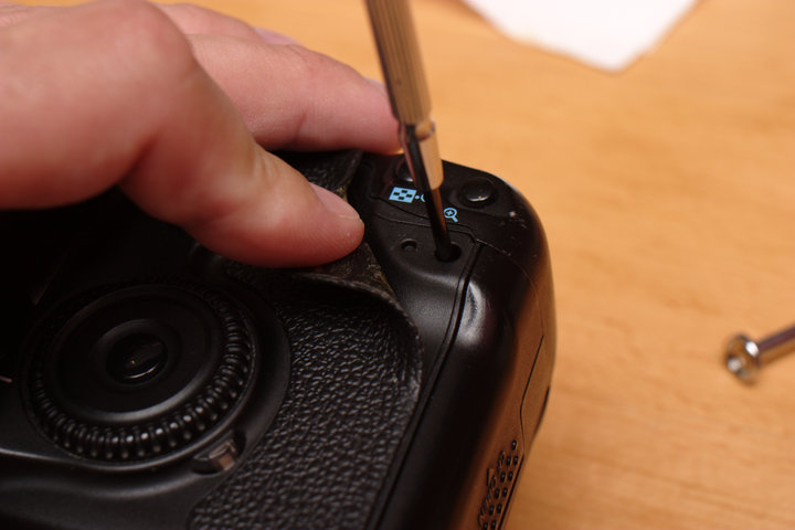
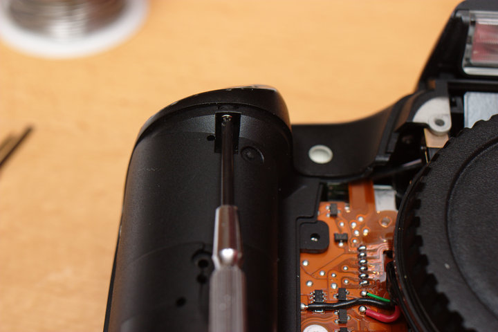
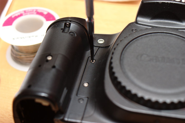
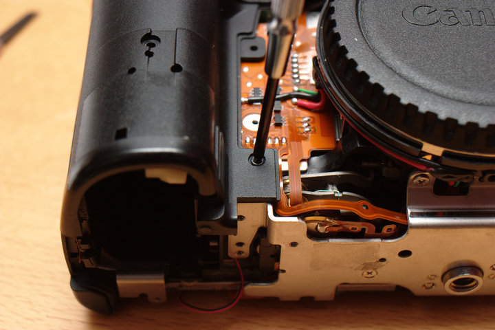 There is also one hiding at the top, holding the top down right next to
the shutter button.
There is also one hiding at the top, holding the top down right next to
the shutter button.
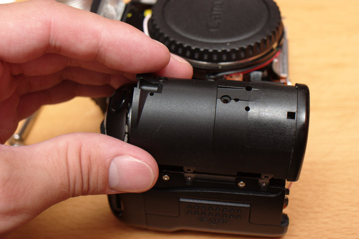
 This part should now come off.
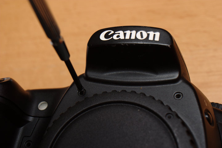
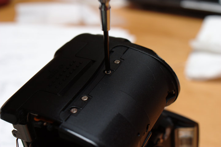
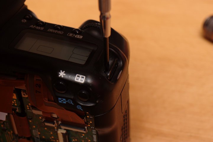
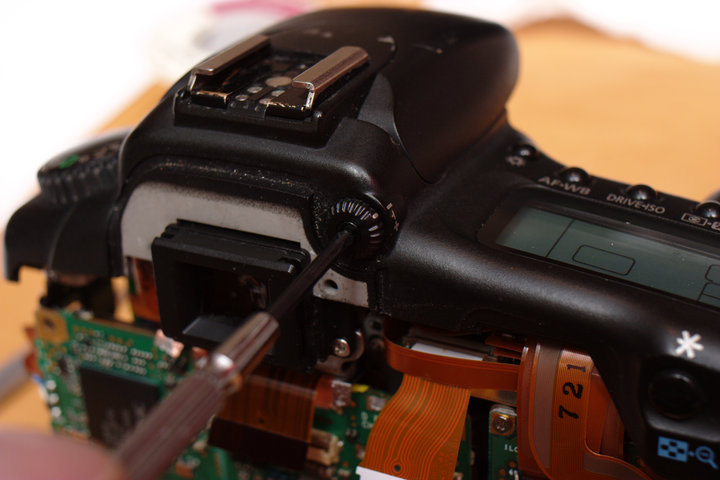
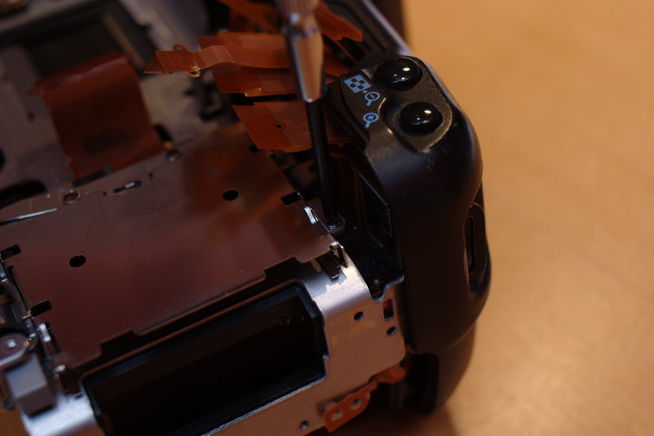
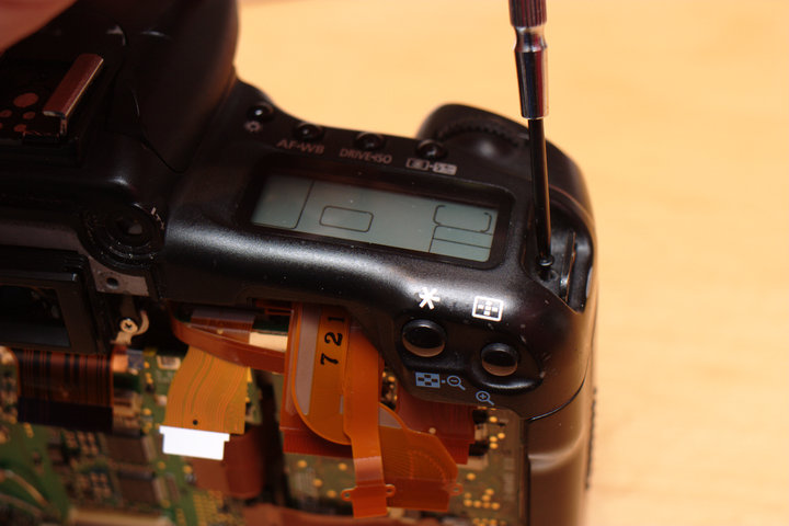
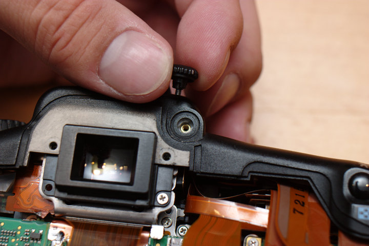
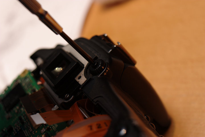
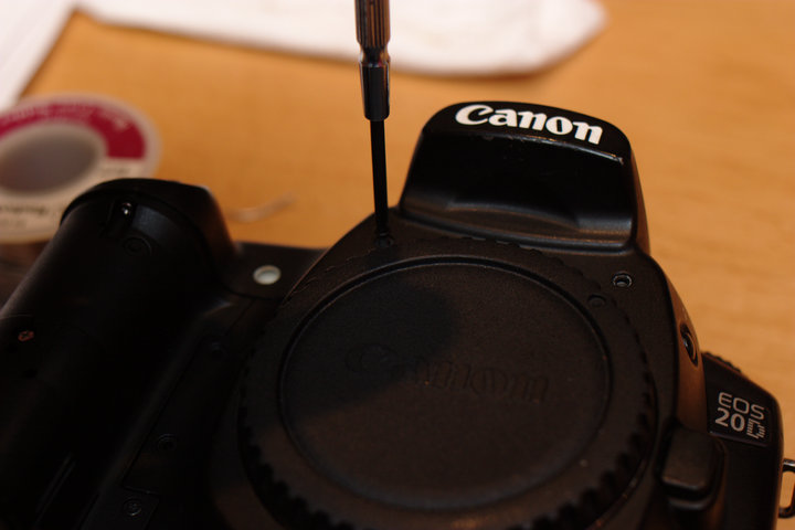
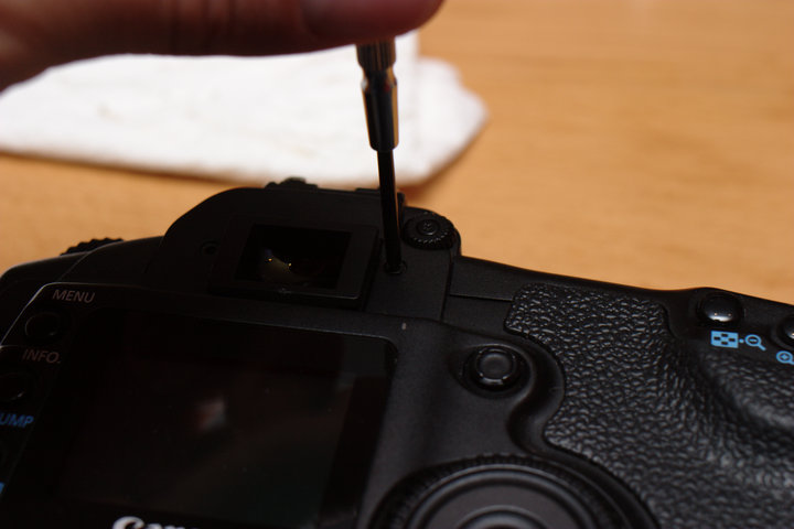
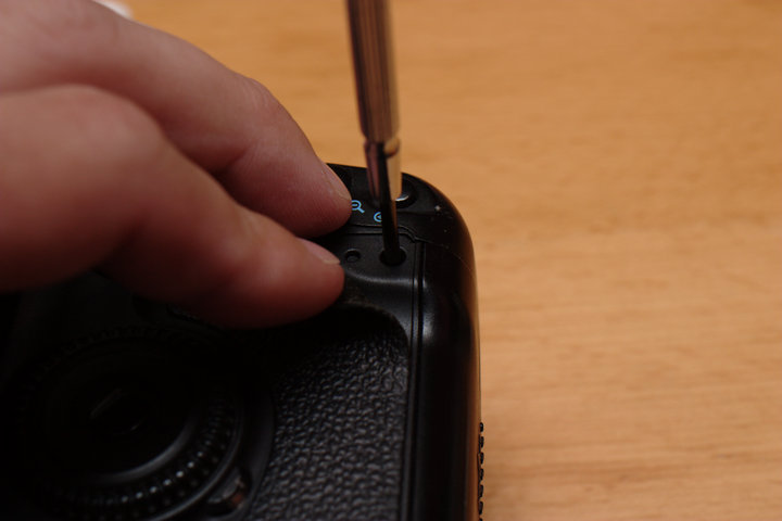
 Prepare to remove the top of the camera by removing the top screw on the
right next to the strap mount and the diopter adjustment knob to the
right of the viewfinder.
Prepare to remove the top of the camera by removing the top screw on the
right next to the strap mount and the diopter adjustment knob to the
right of the viewfinder.
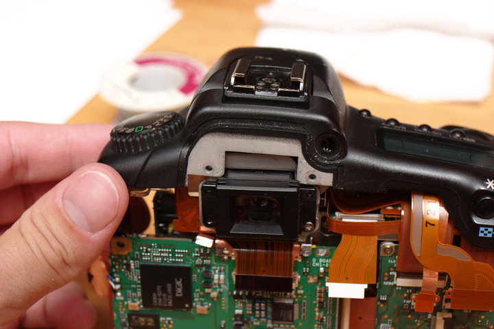
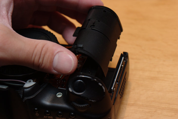
 The top should now be free to remove. Make sure the cables have been
removed on the top of the board on the right, near the CF slot.
The top should now be free to remove. Make sure the cables have been
removed on the top of the board on the right, near the CF slot.
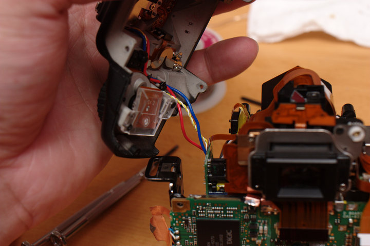
You should be able to lever your fingers against the left side strap mount which is attached to the main frame. NOTE: The top is tethered by wires running to the left (from the back) side of the lens mount. Be careful not to break these wires.
 With the top off, place the camera down resting on the lens mount again.
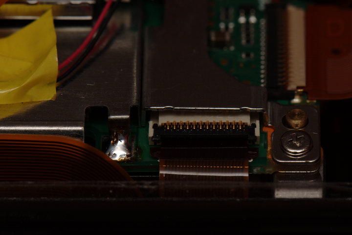
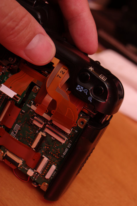
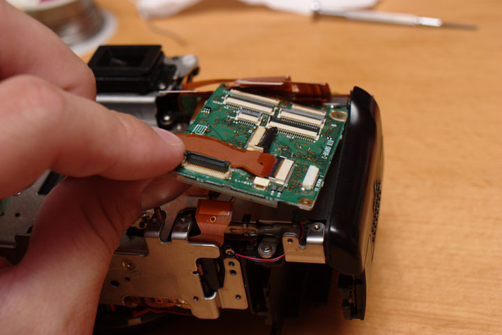
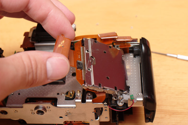
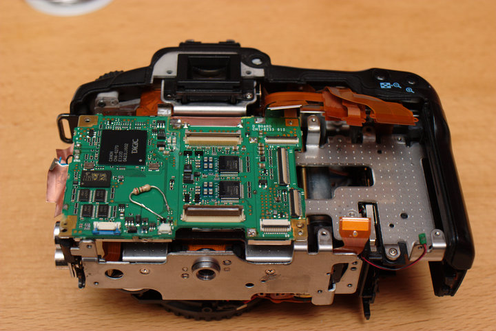
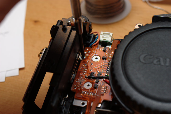
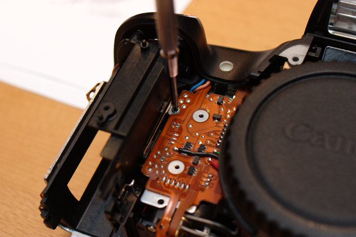
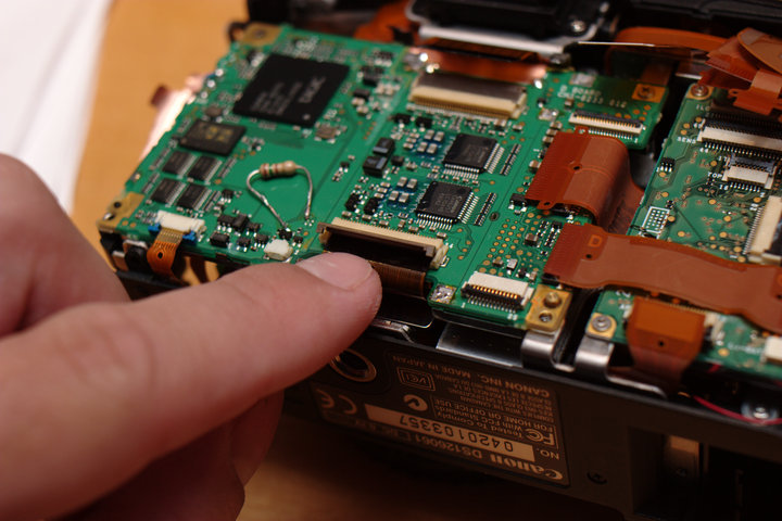
Prepare to remove the left side mainboard by disconnecting the ribbon
cable on the bottom. This connector has two blue pull-out tabs instead
of a lift-up arm. They should pull out like this;
With the top off, place the camera down resting on the lens mount again.
Prepare to remove the left side mainboard by disconnecting the ribbon
cable on the bottom. This connector has two blue pull-out tabs instead
of a lift-up arm. They should pull out like this;
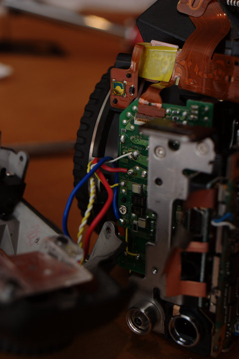
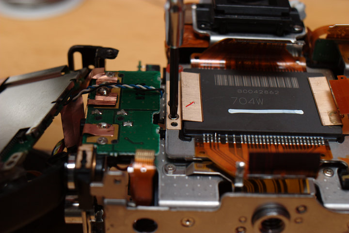
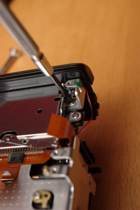
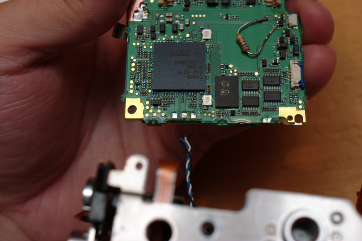
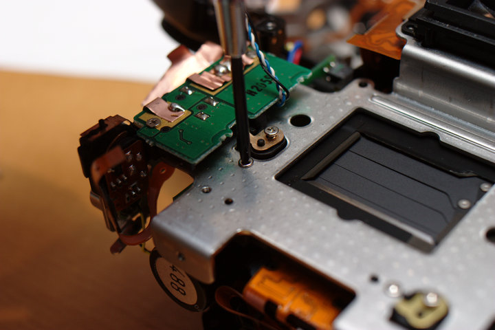
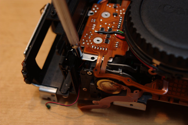
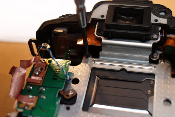
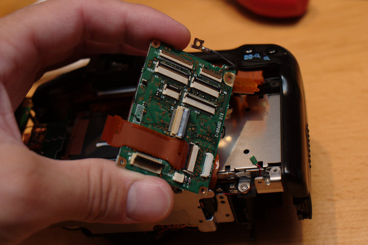
 There should be one screw holding the left side mainboard in place, in
the top right. Remove it, and lift out the board. There will be three
wires tethering this board in place. I broke one wire off during
repeated disassembly/reassembly -- you may wish to desolder them in
advance to avoid dragging the board around.
There should be one screw holding the left side mainboard in place, in
the top right. Remove it, and lift out the board. There will be three
wires tethering this board in place. I broke one wire off during
repeated disassembly/reassembly -- you may wish to desolder them in
advance to avoid dragging the board around.
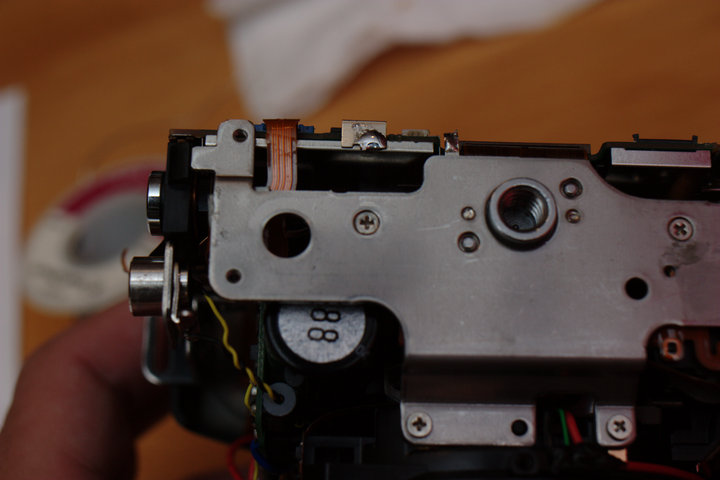
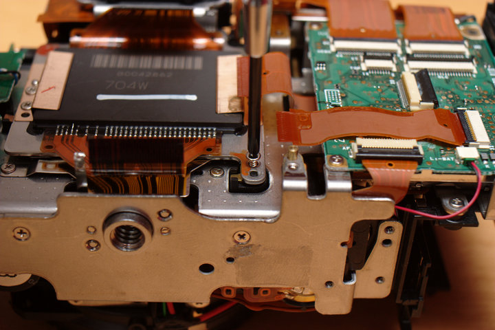
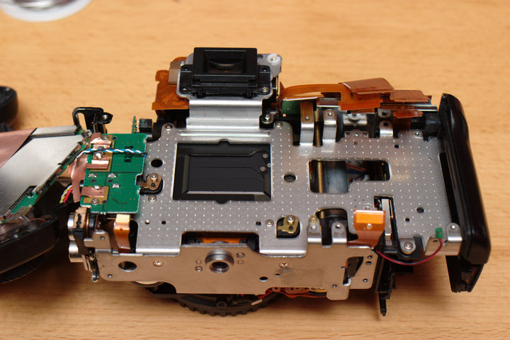
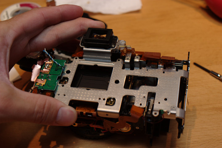
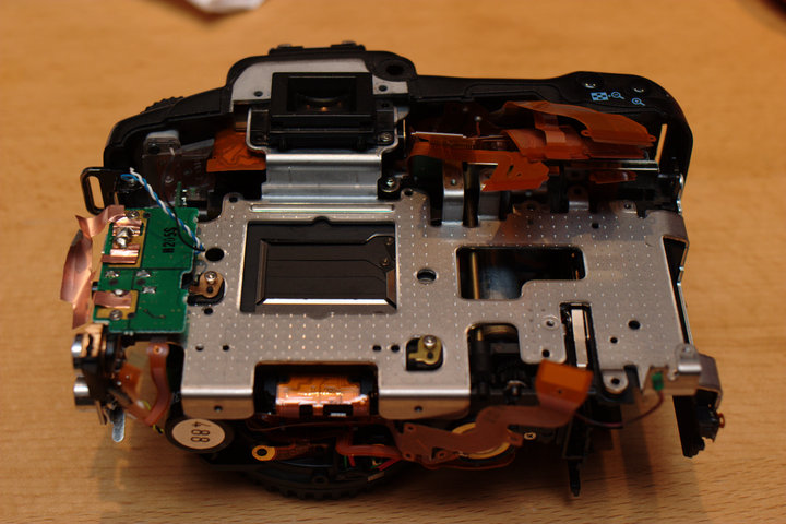
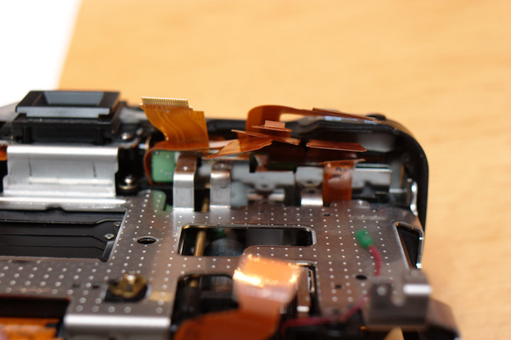
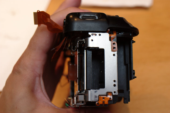
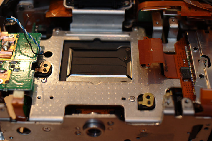
 You should now see the back of the CMOS sensor. On the other side of
that is the shutter! :) Getting closer...
You should now see the back of the CMOS sensor. On the other side of
that is the shutter! :) Getting closer...
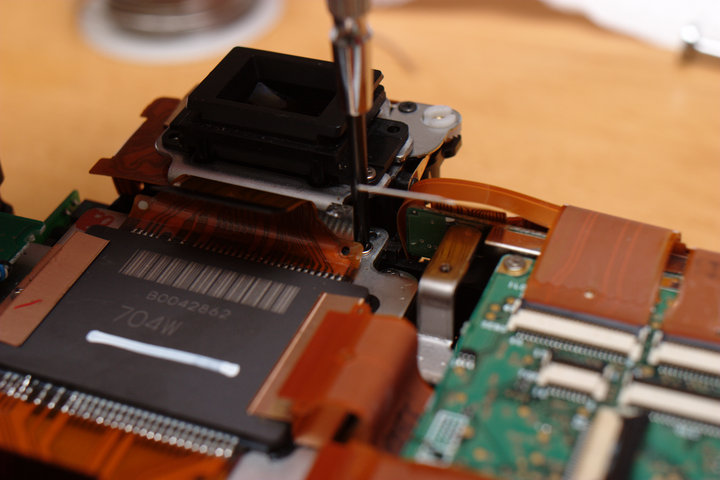
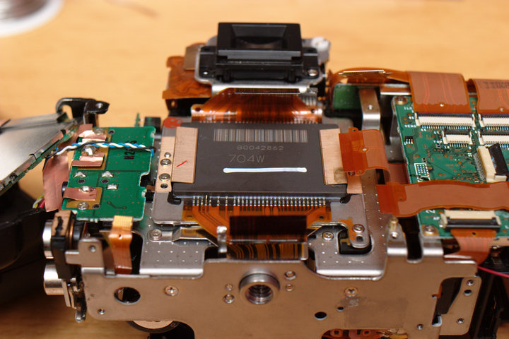 Remove the sensor by freeing the three main screws and one grounding tab
screw that hold it down. Be careful -- under the three screws are shimms
that align the sensor and make it equidistant from the focus sensor (and
focus screen) so that everything lines up. Do not remove, lose, bend, or
rearrange these shimms, or you will be unhappy.
Remove the sensor by freeing the three main screws and one grounding tab
screw that hold it down. Be careful -- under the three screws are shimms
that align the sensor and make it equidistant from the focus sensor (and
focus screen) so that everything lines up. Do not remove, lose, bend, or
rearrange these shimms, or you will be unhappy.
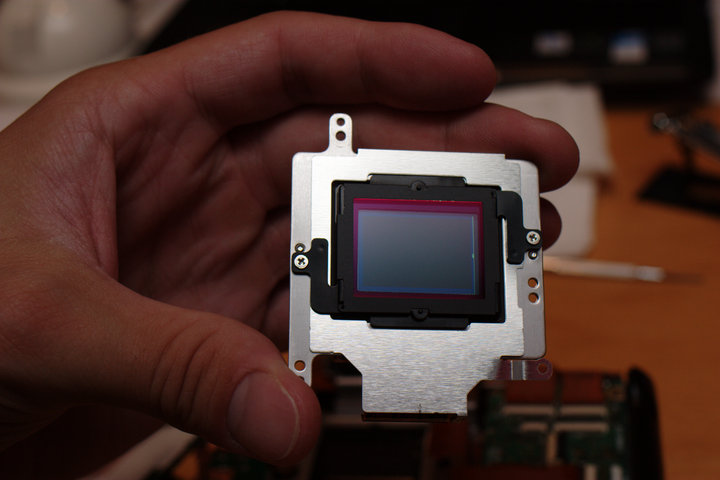
 Sensor cleaning was never this easy! :)
 I put the screws back in (not all the way in -- the holes aren't deep
enough) right after removing the sensor so that I would not lose the
shimms.
I put the screws back in (not all the way in -- the holes aren't deep
enough) right after removing the sensor so that I would not lose the
shimms.
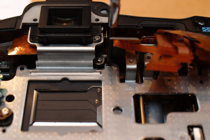
 Well, there is the shutter! Too bad there is a frame holding everything
else in front of it...
Well, there is the shutter! Too bad there is a frame holding everything
else in front of it...
 Remove the right side board with many connectors by removing the top
left, bottom left, and bottom right screws.
Remove the right side board with many connectors by removing the top
left, bottom left, and bottom right screws.
 Oh, wait a second, there is a grounding wire to a screw below. Remove
that screw and then remove the board.
Oh, wait a second, there is a grounding wire to a screw below. Remove
that screw and then remove the board.
 Remove the Compact Flash slot by removing the bottom right screw, top
right screw, and (longer) top left screw.
Remove the Compact Flash slot by removing the bottom right screw, top
right screw, and (longer) top left screw.
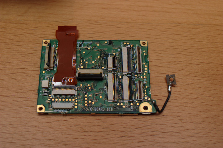
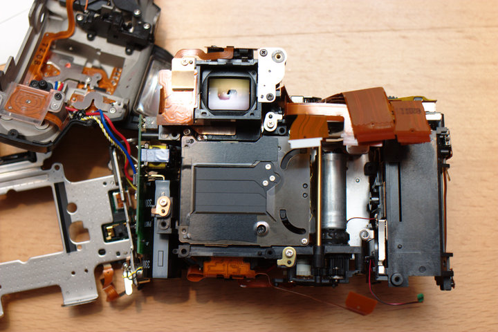
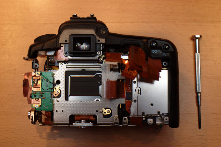
 Starting to look pretty empty...
 I placed the tethered board back in for now in attempt to not break the
wires while working on the sides.
I placed the tethered board back in for now in attempt to not break the
wires while working on the sides.
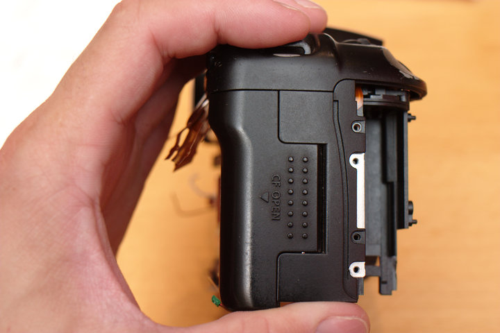
 Remove the Compact Flash side door (two screws).
 Remove the bottom metal plate (four screws).
 Incidentally, this is in the wiring order that main board that I should
have desoldered earlier... :)
Incidentally, this is in the wiring order that main board that I should
have desoldered earlier... :)
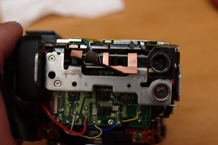
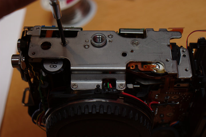
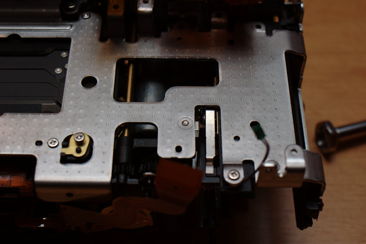
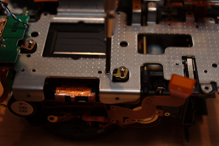
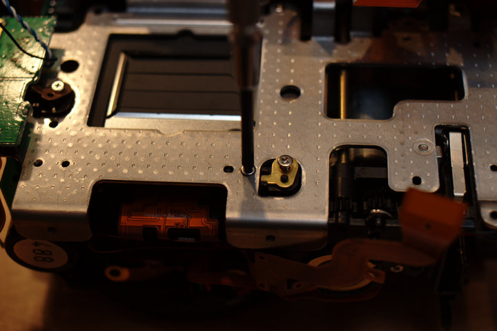
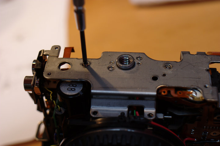
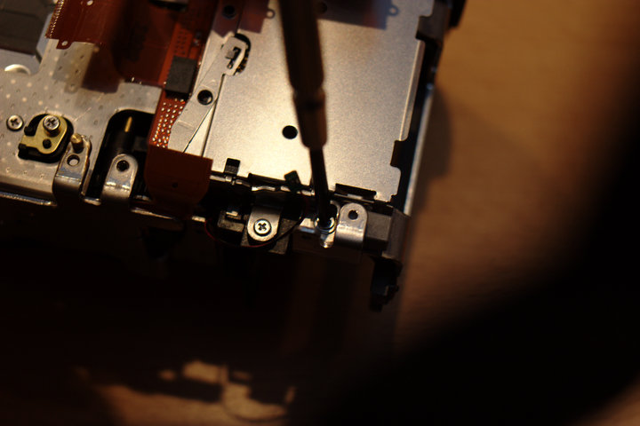
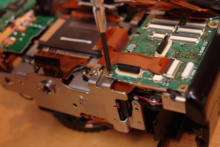
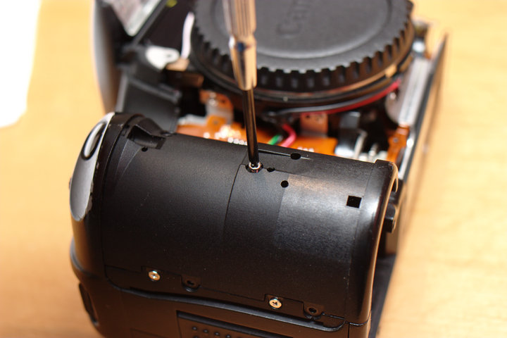
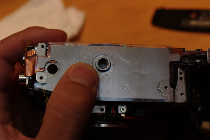
 Now comes the, erm, hack. I call that screw right in the middle of this
picture the "evil screw". It is the only screw holding anything else
screwed to the core mirror box to this frame that is screwed in from the
front side. Unfortunately, to remove this screw properly, we would have
to remove all of the front and top wiring and pretty much get down to the
core mirror box.
Now comes the, erm, hack. I call that screw right in the middle of this
picture the "evil screw". It is the only screw holding anything else
screwed to the core mirror box to this frame that is screwed in from the
front side. Unfortunately, to remove this screw properly, we would have
to remove all of the front and top wiring and pretty much get down to the
core mirror box.
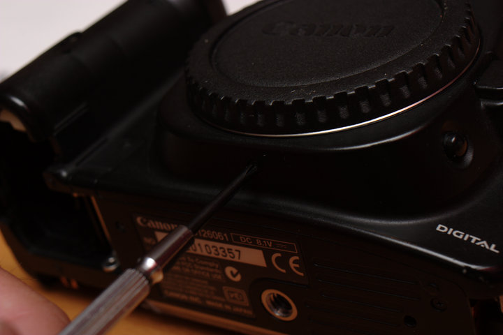
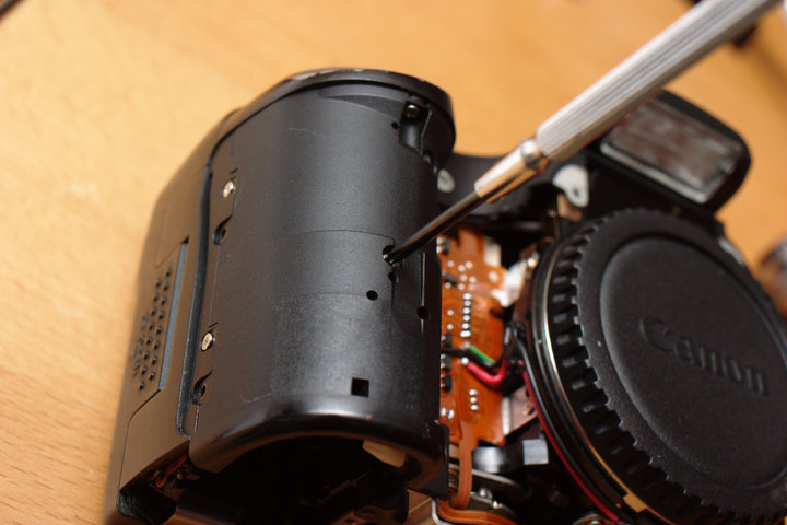
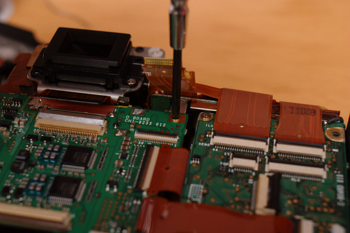
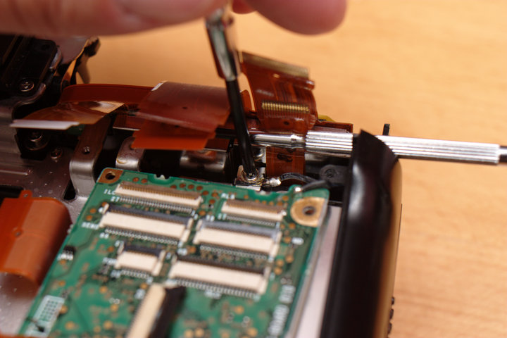
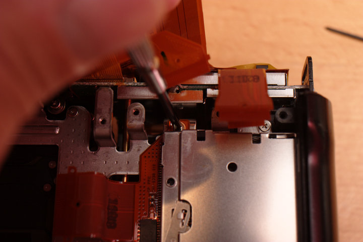
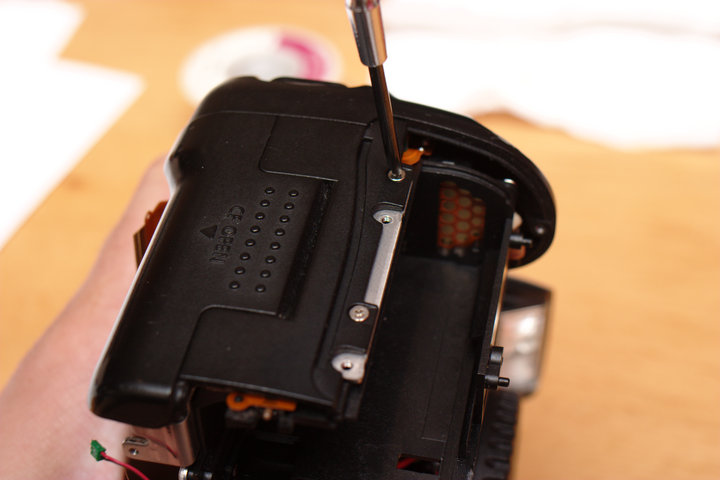
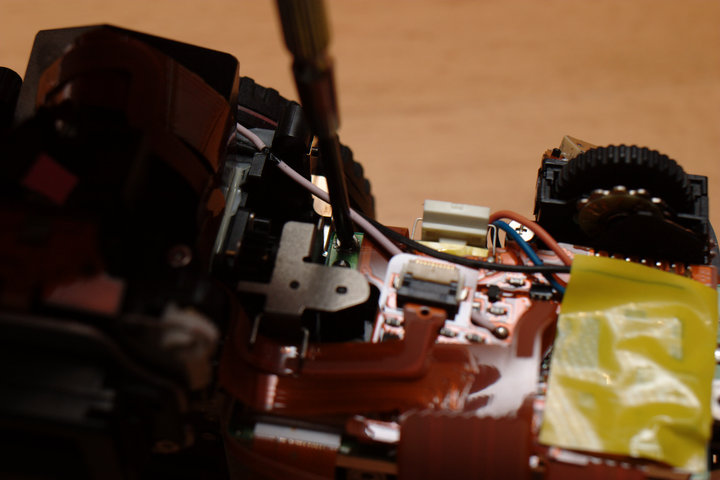
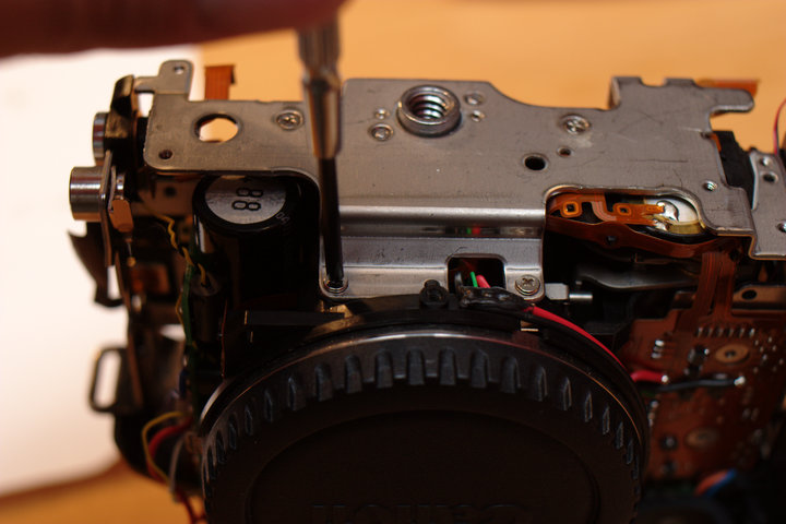
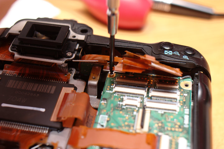
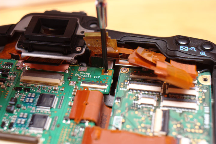
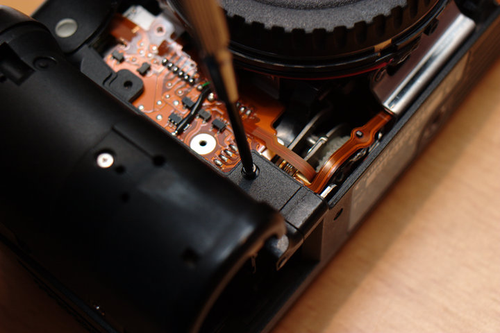
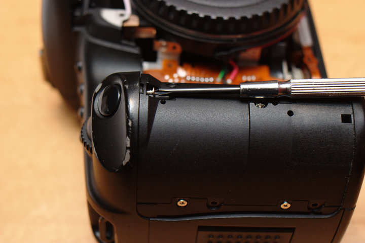
 After much frustration, I decided to cheat. There is almost enough gap
from the front of the camera to sneak screwdriver in at a slight angle,
but not quite. By freeing the right side a little, we can get it in
there. Remove the two top right board screws.
After much frustration, I decided to cheat. There is almost enough gap
from the front of the camera to sneak screwdriver in at a slight angle,
but not quite. By freeing the right side a little, we can get it in
there. Remove the two top right board screws.
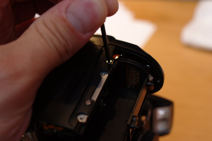
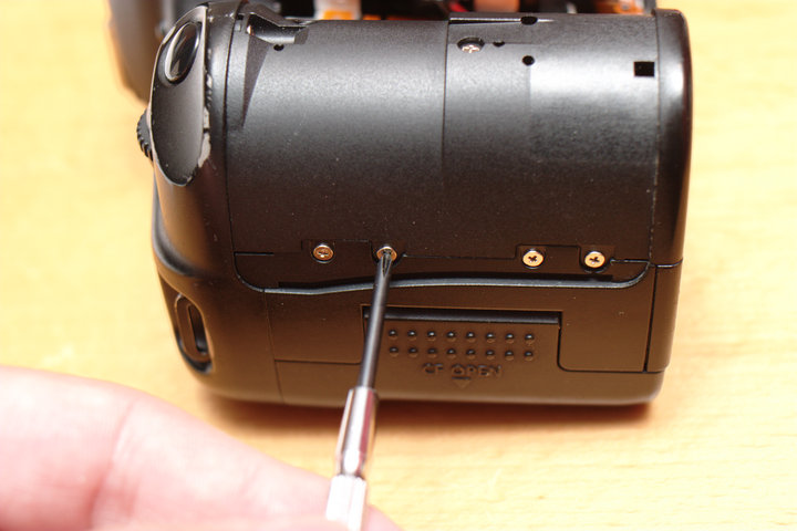
 Remove the screw holding the battery compartment to the frame.
 Remove the back screw holding the battery compartment to the frame.
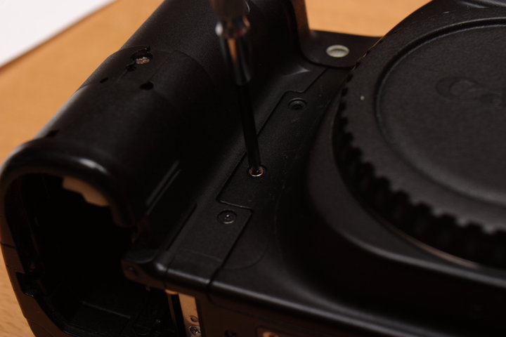
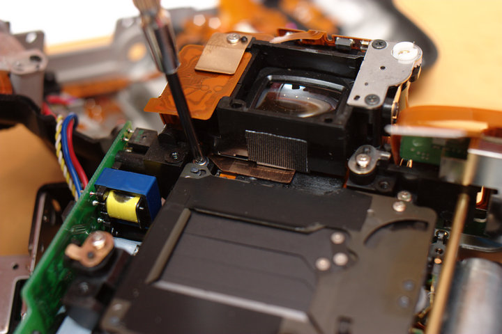
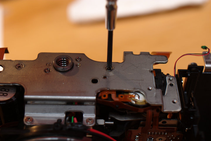
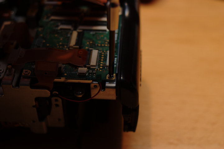
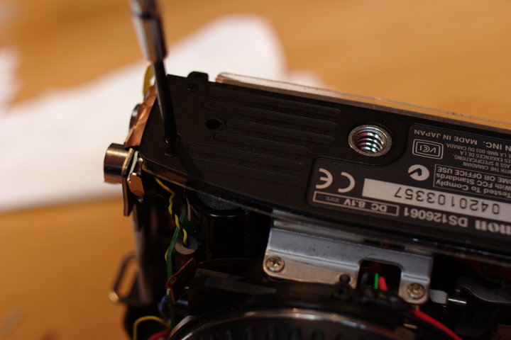
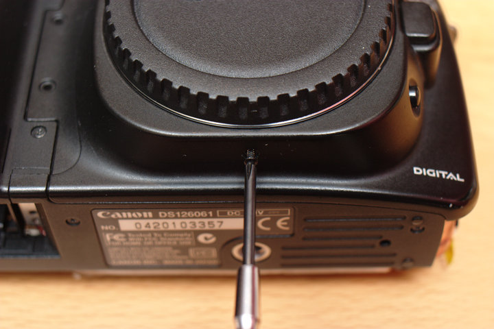
 Here is a picture of the evil screw from the front.
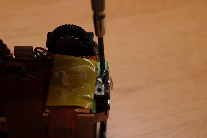
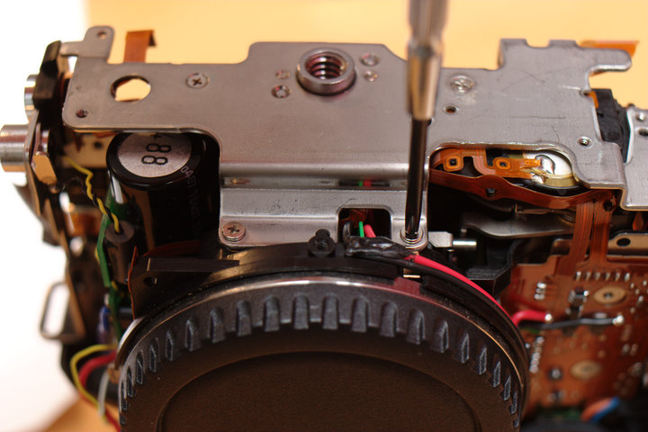
 Here is how I got it out. (Sorry, Canon...)
 There it is, in all of its glory.
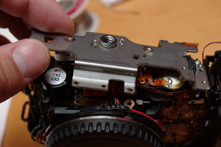
 Now, back to the back again, we can remove the rest of the frame screws.
There should be four remaining of the six total since we removed the one
holding the ground tab and the one earlier to help get out the evil screw.
Now, back to the back again, we can remove the rest of the frame screws.
There should be four remaining of the six total since we removed the one
holding the ground tab and the one earlier to help get out the evil screw.
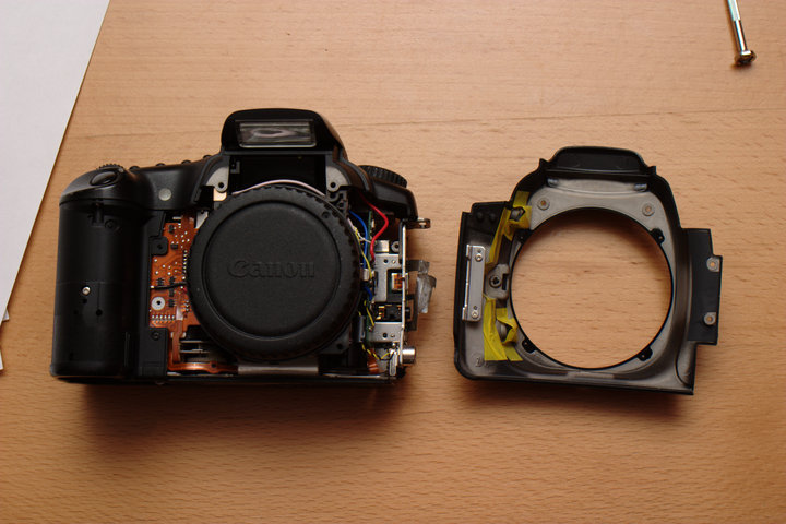
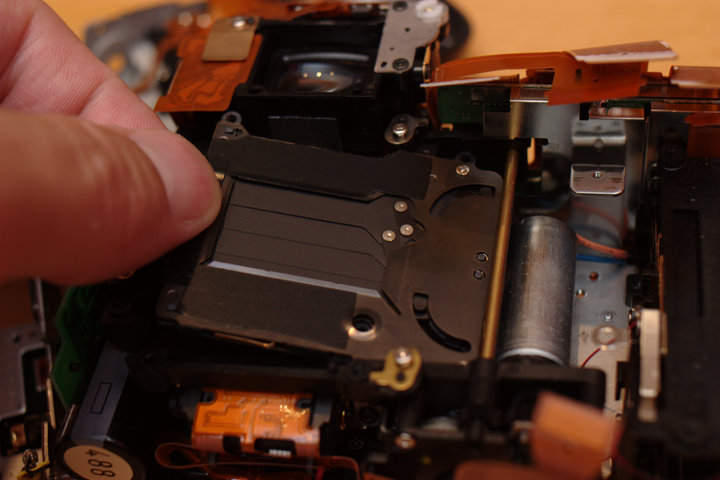
 The frame should now separate from the mirror box.
 There we are -- the shutter!
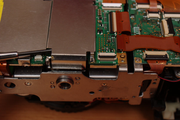
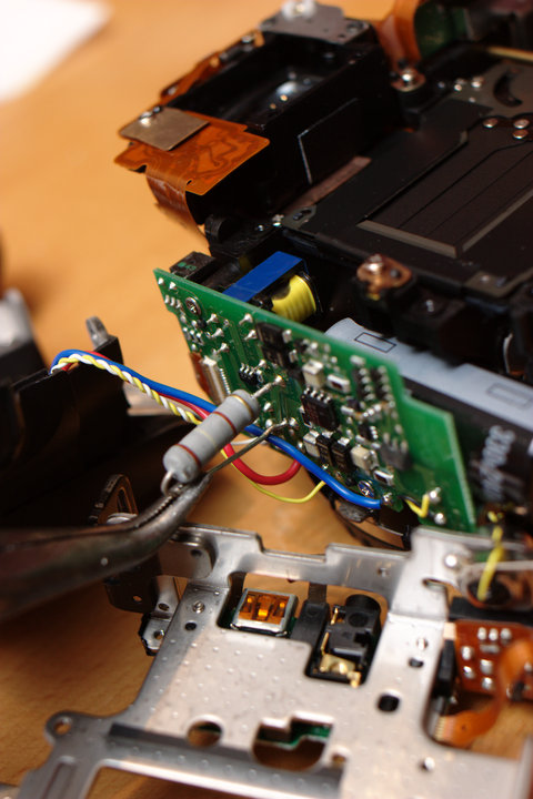
 STOP! Don't touch! Discharge the flash capacitor with a resistor before
you go and zap yourself. I used this 1 Watt resistor that I use for this
sort of thing. Don't just short it, or you'll fry something and harm the
capacitor.
STOP! Don't touch! Discharge the flash capacitor with a resistor before
you go and zap yourself. I used this 1 Watt resistor that I use for this
sort of thing. Don't just short it, or you'll fry something and harm the
capacitor.
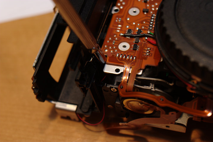
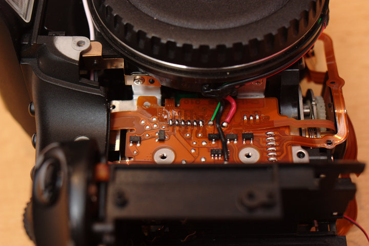
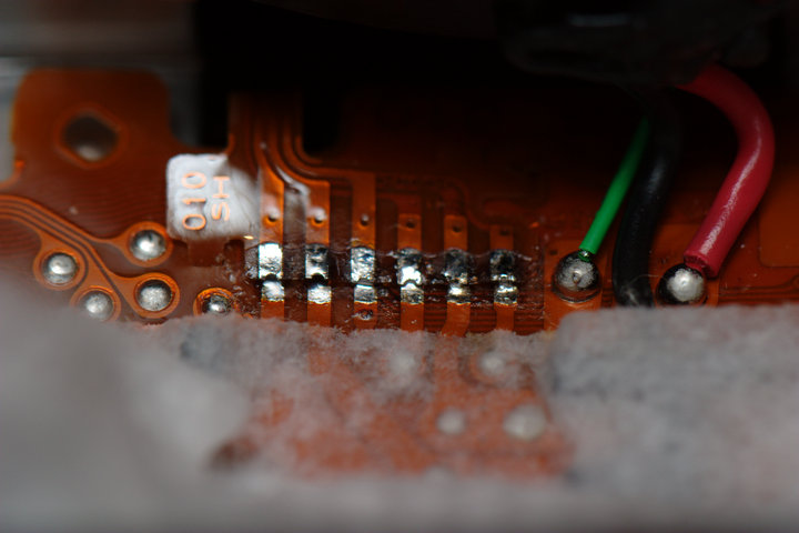
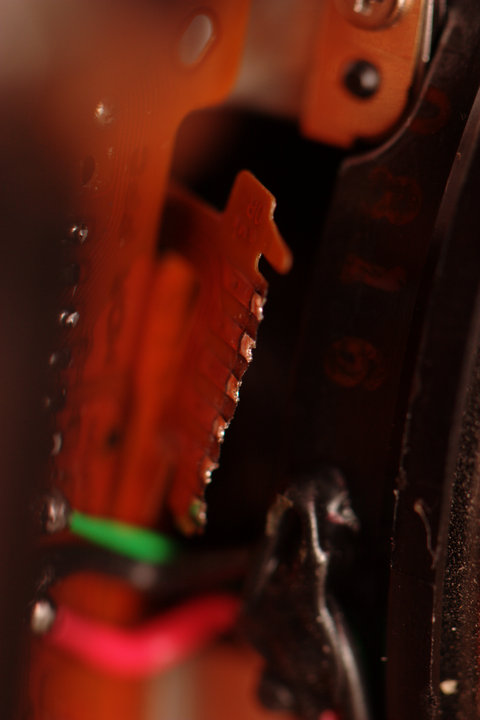
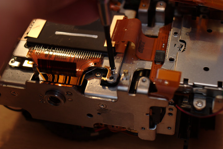
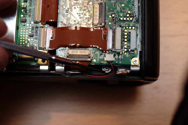
 You could try to remove the shutter now, like I did, but you'll find that
is still attached by a ribbon cable to the front side of the camera.
You'll need to desolder it here.
You could try to remove the shutter now, like I did, but you'll find that
is still attached by a ribbon cable to the front side of the camera.
You'll need to desolder it here.
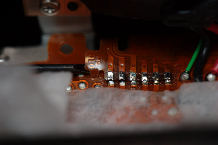
 This is the best I could do with a desoldering iron.
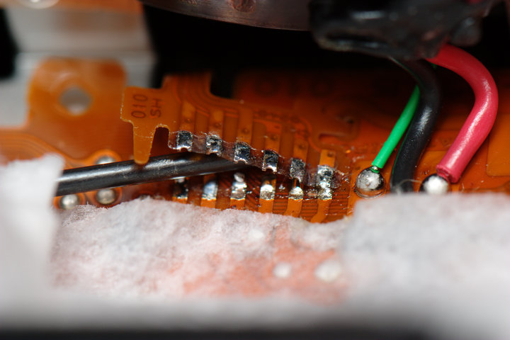
 I carefully ran under the connection with a flat blade screwdriver while
heating briefly it with the soldering iron to free the sticky
connections.
I carefully ran under the connection with a flat blade screwdriver while
heating briefly it with the soldering iron to free the sticky
connections.
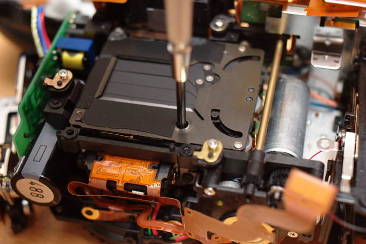
 Now remove the three screws holding the shutter in place and remove it.
 My new shutter part did not come with this ribbon wire bit, so I had to
move it from the old to the new. Follow the same procedure to remove the
wire from the shutter unit end.
My new shutter part did not come with this ribbon wire bit, so I had to
move it from the old to the new. Follow the same procedure to remove the
wire from the shutter unit end.
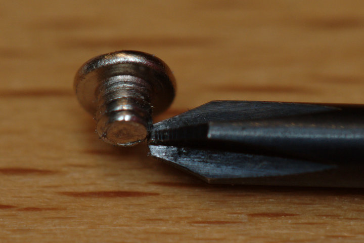
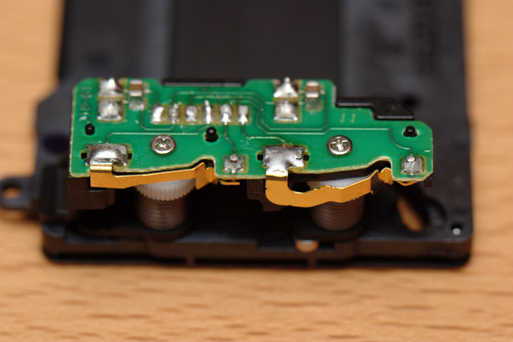
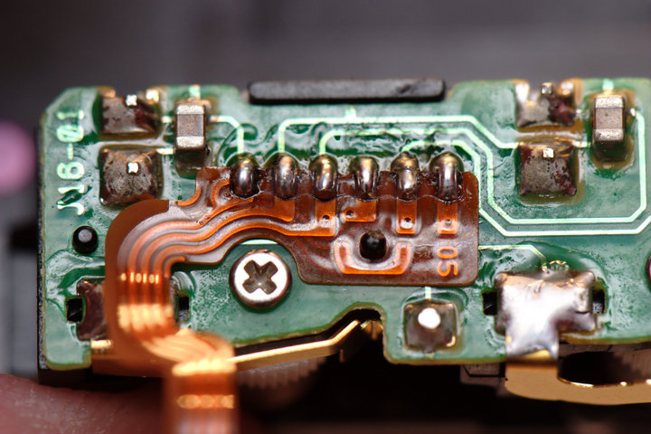
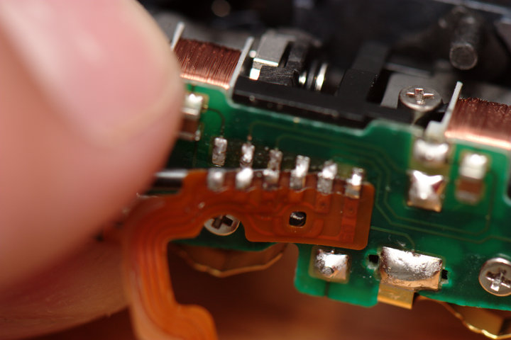 Here is what went wrong with my shutter. The gold-plated bit on the right
broke off at the 90 degree angle from the board.
Here is what went wrong with my shutter. The gold-plated bit on the right
broke off at the 90 degree angle from the board.
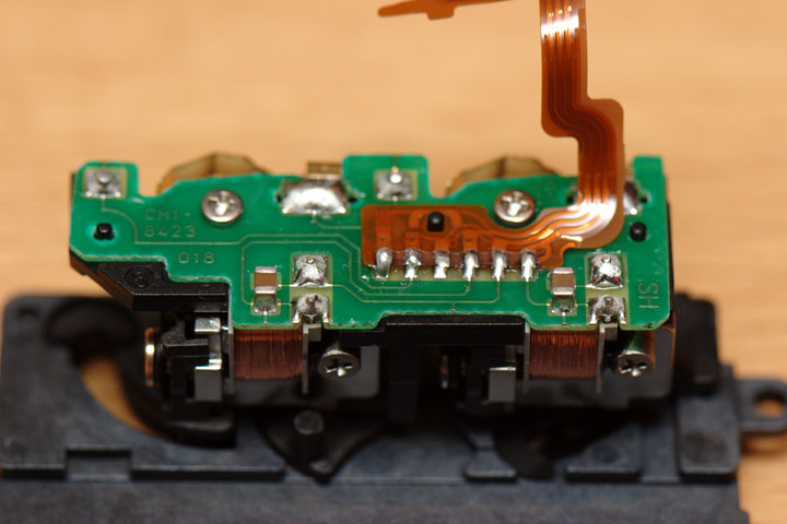
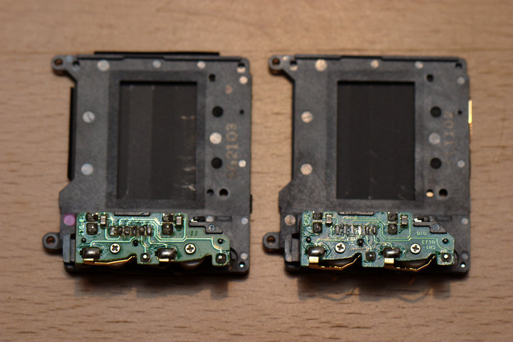
 Here is old (~50,000 cycles) and (~10,000 cycles) new from above. Note
that the newer unit has bigger gold-plated contacts.
Here is old (~50,000 cycles) and (~10,000 cycles) new from above. Note
that the newer unit has bigger gold-plated contacts.
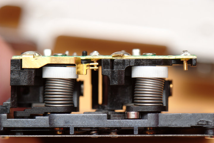
 Since I am trying to fix the newer unit here, I decided to move one of
the gold bits from the newer unit to the older unit. My Frankenstein
shutter now looks like this:
Since I am trying to fix the newer unit here, I decided to move one of
the gold bits from the newer unit to the older unit. My Frankenstein
shutter now looks like this:
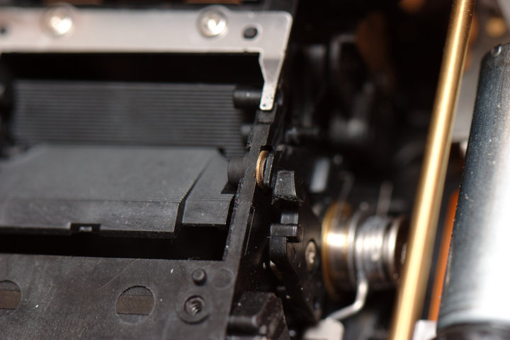
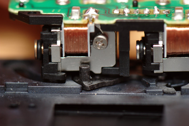
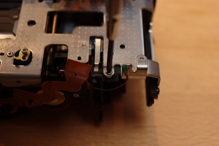
 NOTE: The shutter has a little arm on it here that is mechanically linked
to a fork-like arm on the right of the mirror box. You can move the arm
on the shutter unit with your finger (carefully!), but make sure that it
is lined up with the "hand" on the mirror box end before reinstallation.
NOTE: The shutter has a little arm on it here that is mechanically linked
to a fork-like arm on the right of the mirror box. You can move the arm
on the shutter unit with your finger (carefully!), but make sure that it
is lined up with the "hand" on the mirror box end before reinstallation.
 I moved the wire back to my other shutter unit here. Make sure the ends
of the wire also do not have any large solder blobs that will make the
cable not sit flat when reinstalled.
I moved the wire back to my other shutter unit here. Make sure the ends
of the wire also do not have any large solder blobs that will make the
cable not sit flat when reinstalled.
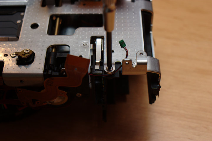
 Prepare to reinstall the shutter by checking the arm alignment and then
placing in while using a small screwdriver or other object to poke
through the ribbon cable to the front side as before.
Prepare to reinstall the shutter by checking the arm alignment and then
placing in while using a small screwdriver or other object to poke
through the ribbon cable to the front side as before.
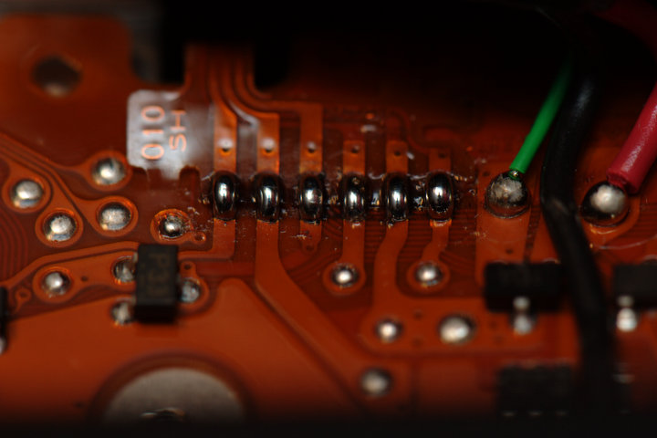
 Solder back in place the shutter unit connection. I slid it into the
holders first and then solder-blobbed all of the points.
Solder back in place the shutter unit connection. I slid it into the
holders first and then solder-blobbed all of the points.
 "Reinstallation is reverse of removal." Screw back in the (new) shutter
and place the frame back over. Make sure all of the ribbon cables are
there and not smushed under something.
"Reinstallation is reverse of removal." Screw back in the (new) shutter
and place the frame back over. Make sure all of the ribbon cables are
there and not smushed under something.
 Get that evil screw back in first, while everything is still loose.
 This front side screw.
 Your ribbon cables should all be there...
 The five frame screws (except the one with the ground tab).
 Two top screws on the right.
 I put the top on loosely at this point so that I can turn the camera
over. Reinstall the bottom plate and four screws.
I put the top on loosely at this point so that I can turn the camera
over. Reinstall the bottom plate and four screws.

 Reinstall the Compact Flash slot (three screws -- top left one
longer).
Reinstall the Compact Flash slot (three screws -- top left one
longer).
 Reinstall the slot door cover with two screws.
 Break for a beverage and wash your hands. :)
 Great time to clean the sensor.
 Remove the three screws holding the shimms down and make sure the shimms
are still aligned over the plastic posts.
Remove the three screws holding the shimms down and make sure the shimms
are still aligned over the plastic posts.
 Reinstall the sensor and tighten equally the three screws. These are
three screws you do not want to strip.
Reinstall the sensor and tighten equally the three screws. These are
three screws you do not want to strip.
 There is one grounding tab at the bottom left as well.
 Reinstall the connector board on the right. Install the ground tab with
the sixth frame screw first.
Reinstall the connector board on the right. Install the ground tab with
the sixth frame screw first.
 Then align the board and screw in the top left, bottom left, and bottom
right screws.
Then align the board and screw in the top left, bottom left, and bottom
right screws.
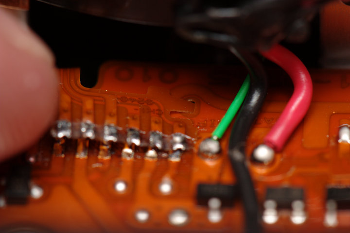
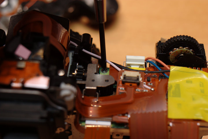
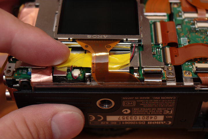
 Prepare the main board for reinstallation. If you desoldered it, black
is GND, white is D-, blue is D+.
Prepare the main board for reinstallation. If you desoldered it, black
is GND, white is D-, blue is D+.
 Screw in the top right screw (the only screw for now).
 Screw down the top and reinstall the diopter adjustment knob.
 Reinstall the front side hand grip. One screw on the front, one in the lower
front near the lens mount, two on the side, and one into the top.
Reinstall the front side hand grip. One screw on the front, one in the lower
front near the lens mount, two on the side, and one into the top.
 Reattach the sensor cables and the rest of the cables, while you are at
it.
Reattach the sensor cables and the rest of the cables, while you are at
it.
 Solder the shielding back in place.
 I decided to put back the copper shielding tape this time.
 Restick the bottom pad.
 Screw back in the bottom plastic cover.
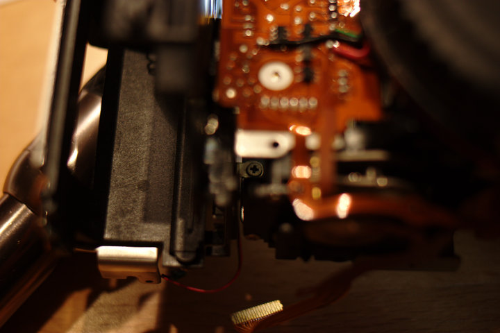
 Make sure the cables are all in place and not going to catch on anything.
Here, the power cable from the battery would get caught in the cover lip
if not pushed down further.
Make sure the cables are all in place and not going to catch on anything.
Here, the power cable from the battery would get caught in the cover lip
if not pushed down further.
 Reinstall the front cover after making sure the wires are all in place
and clear. One of the buttons on the side of the lens mount fell off as
it was only held on by friction on the plastic posts.
Reinstall the front cover after making sure the wires are all in place
and clear. One of the buttons on the side of the lens mount fell off as
it was only held on by friction on the plastic posts.
 Put the side I/O cover in place at around the same time, since it is
easier with the front still loose. Then, reinstall the two screws at the
top, two at the side, one at the bottom to secure the front.
Put the side I/O cover in place at around the same time, since it is
easier with the front still loose. Then, reinstall the two screws at the
top, two at the side, one at the bottom to secure the front.
 Reinstall the LCD.
 The LCD has only one screw on the lower left for now, and shielding
solder point on the top right.
The LCD has only one screw on the lower left for now, and shielding
solder point on the top right.
 Reinstall the back cover.
 Reinstall the two screws around the viewfinder, one on the left, one on
the right under the rubber grip, and two on the bottom.
Reinstall the two screws around the viewfinder, one on the left, one on
the right under the rubber grip, and two on the bottom.
 Reinstall the battery door holder (two screws) and door.
 Reinstall the two screws holding the I/O panel in place.
 Reinstall the front rubber grip.
 Done!
Install the clock battery and a normal battery (you need no flash card or
lens for now), and fire it up! Good luck!
Done!
Install the clock battery and a normal battery (you need no flash card or
lens for now), and fire it up! Good luck!